Wednesday, October 26, 2016

Updated Track

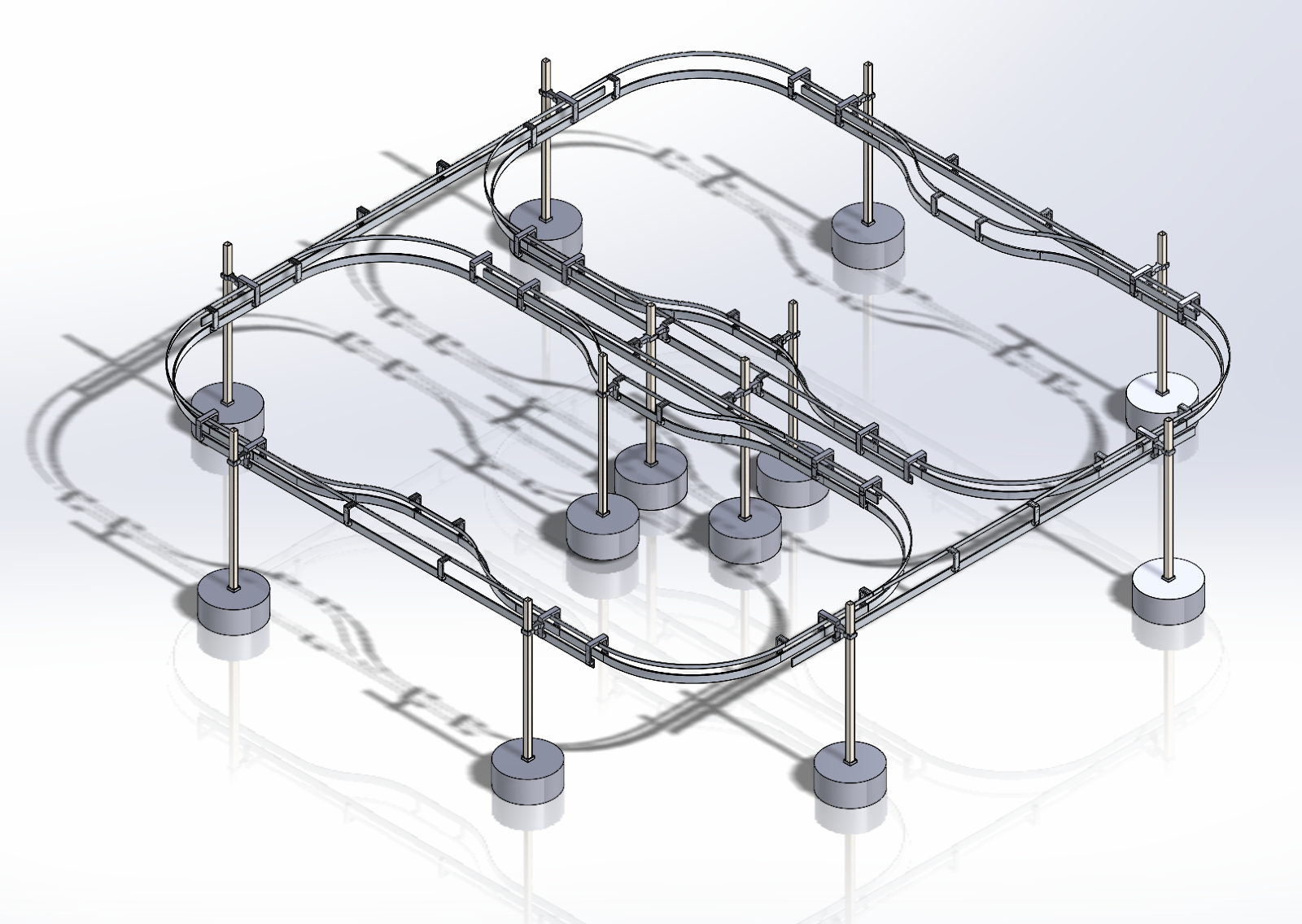
For the previous week, I have updated the track to incorporate the changes with the bracket changes that have been done.  I made three different assemblies that will make putting the track together easier in terms of mating on Solidworks. There are three assemblies: station, corner, and loop connector.  These assemblies consist of both top and bottom rails.  Pictures are shown below of the progress.  Also some time has been put into updating the power point to get ready for presentations for today.

Wednesday, October 19, 2016

Full Track Assembly

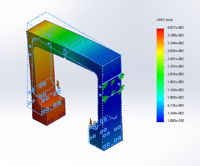
This week I was able to fully assemble the track which will be shown in figure 1.  I still need to run finite element analysis in order to understand how deformations will happen and where support posts will be needed the most.  I also did FEA on the U-bracket we designed to see how it would perform which is shown in figure 2.  From what it looks, the way it is currently mounted would cause one side to have more stress.  We might have to consider another way to mount these brackets.  For both track and U-bracket, aluminum 6061 was used to run the test. One thing that has not been looked into is other material use. I've looked into it briefly but have not read enough to actually make comparisons.

Figure 1: Full track assembly

Figure 2: FEA on U-Bracket

Wednesday, October 12, 2016

Progress 10/12/16

This week was quite slow for us. Due to presentations and midterms, I was not able to work on the project as much. I will soon post the updated track layout in the 12th scale archive so others will have access to it. One thing that needs to be worked on is running FEA so we can determine if the track layout has sufficient stand support.  Once FEA is done, we should be getting into our rapid prototyping.

Wednesday, October 5, 2016

Progress 10/5/2016

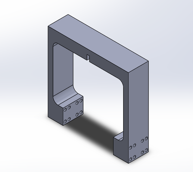
For this week, I worked on designing a bracket that will help keep the width of the track uniform at the end of the bends.  We noticed that the width vary through out the track causing the bogie to work more at tighter widths.  These brackets are meant to be welded on instead of screwed in.  I also worked on getting a two loop track together but the connector between loops is not done yet. Pictures of CAD work is shown below.

Figure 1: ISO view of bracket

Figure 2: Dimensions of bracket
Figure 3: Two loop Track

Tuesday, September 27, 2016

Starting To Design 9/28/2016

For this week, I  started to put together CAD drawings.  I put together a single loop to give an understanding of what our track would look like.  Although there are drawings,  there are still a lot of drawings that still need to be done.  In the next weeks,  drawings of new brackets and guide ways should be done.

Wednesday, September 21, 2016

Progress 9/21/16

The last couple weeks have been a slow start on the project.  But I have taken a look at the previous designs and seeing how the track can be made more efficiently. The goals for the upcoming week is to get most of the CAD designing out of the way so we can have a solid idea of how easy or hard building this track may be.  Once CAD files are done for the track, other teams such as bogie and controls can work to implement their ideas.

Wednesday, September 14, 2016

Getting Started

For this week, I was able to take a look at the previous years CAD files to get a feel of how the track was designed.  One thing that needs to be addressed is tolerances.  Seems like tolerance was forgotten to be considered and caused quite a bit of problems while making the track.  Having access to previous CAD files allows us to stay away from making those mistakes.  As the weeks go on, I should be able to have CAD files of the changes to what the track improvement team thinks are better designs.